Front end tear down…

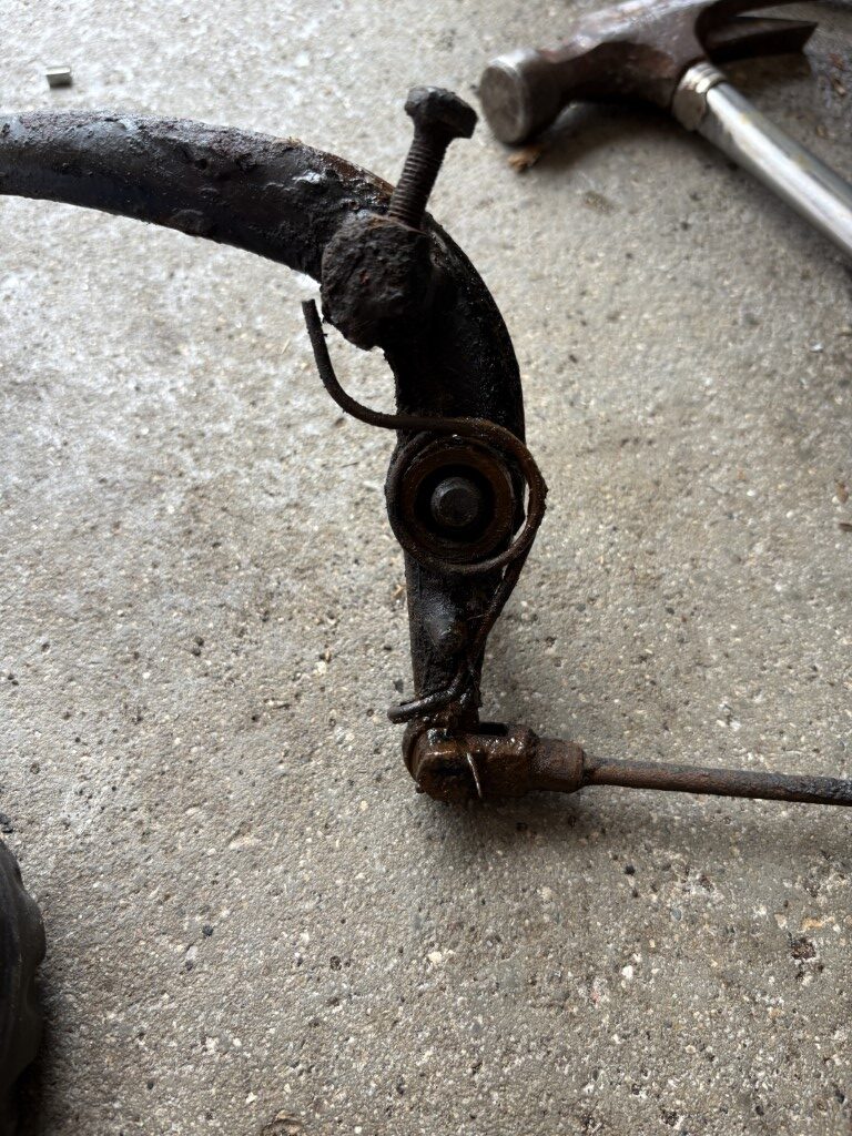
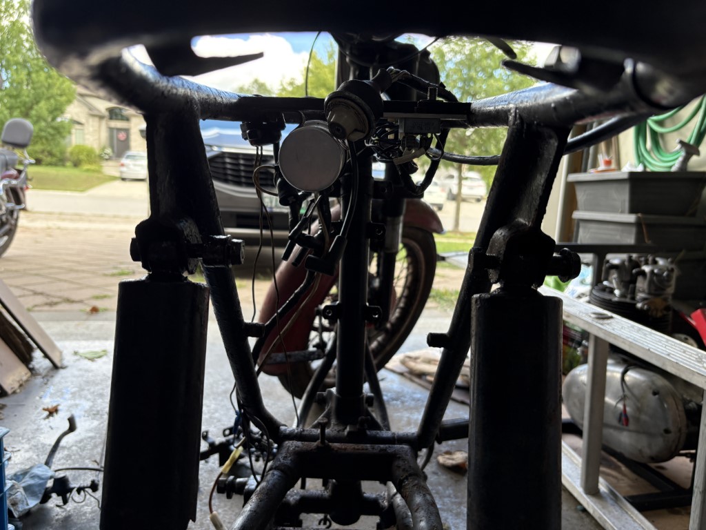
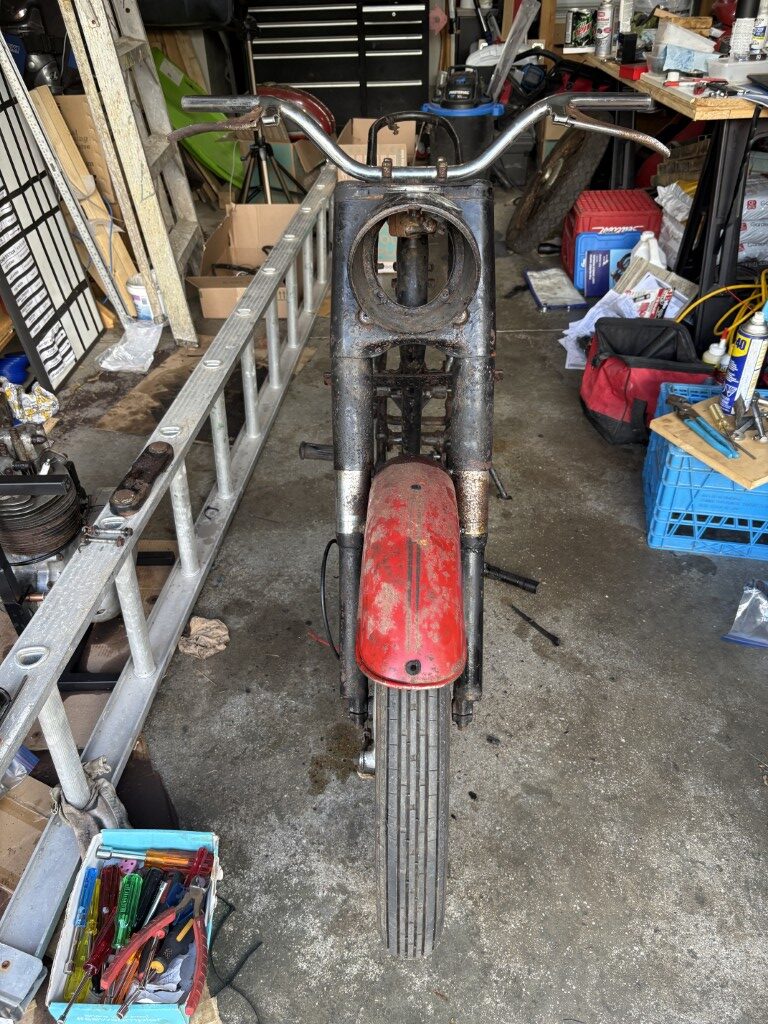
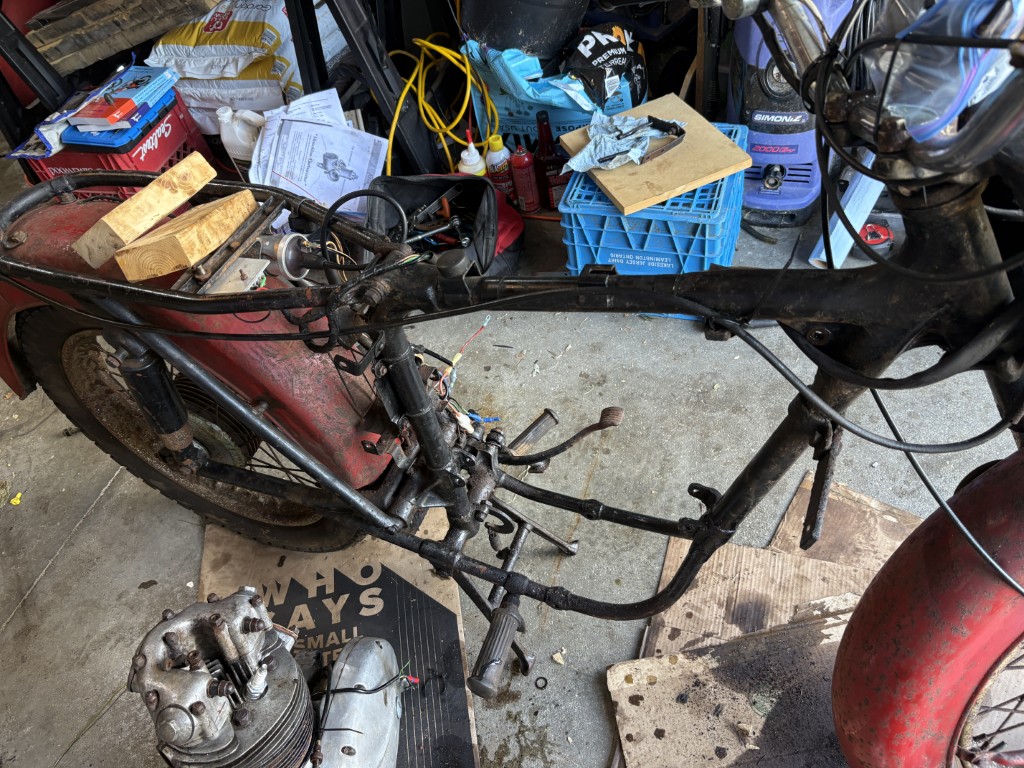
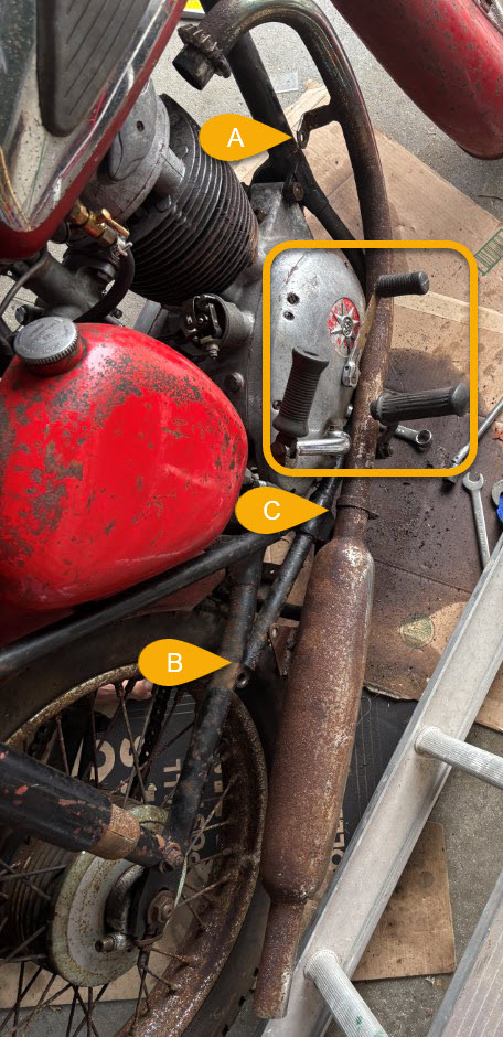
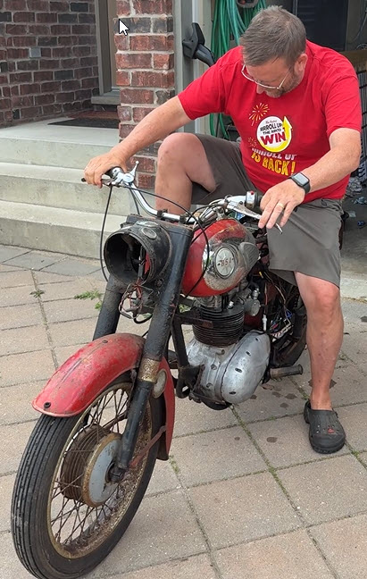
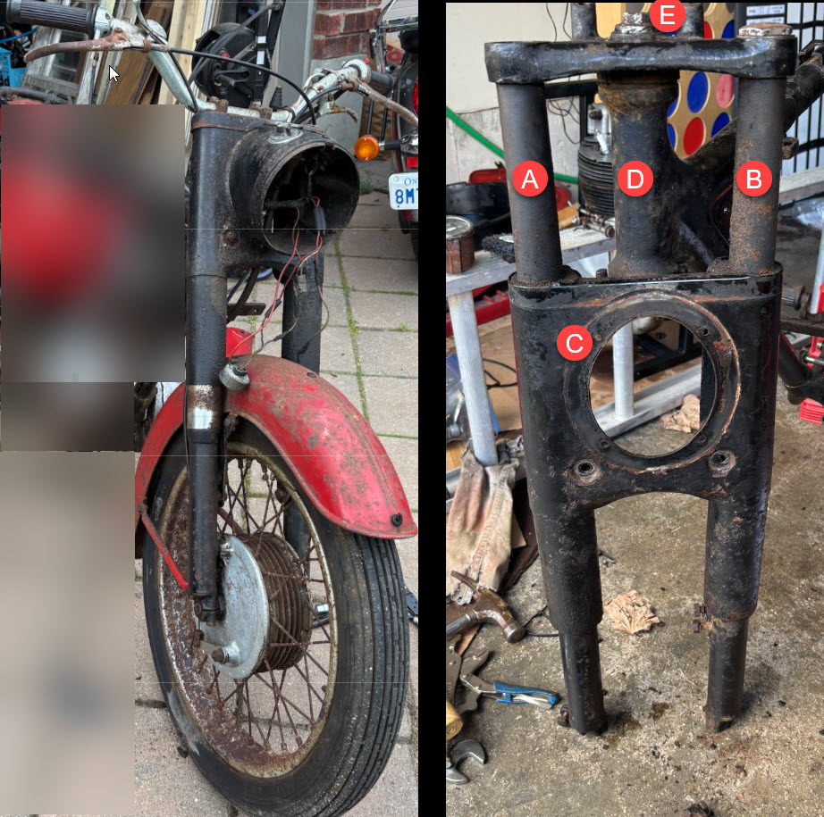
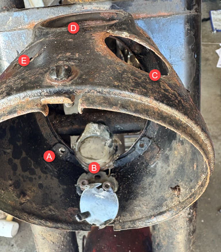
Goal was to strip down the front end and be left with both (A) and (B) as the front suspension removed from the assembly.

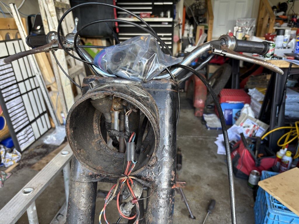
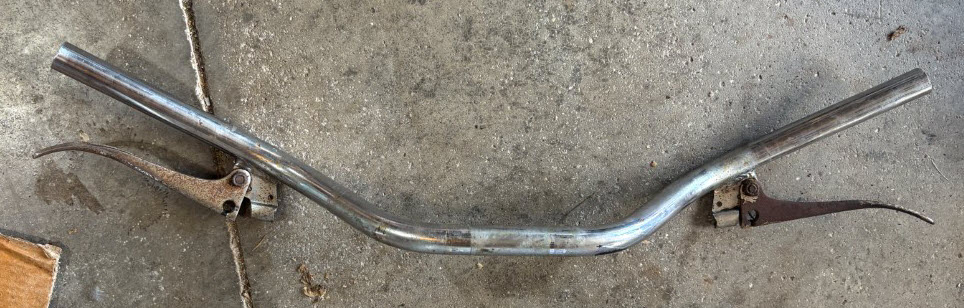
Removal of the handlebars did not pose any issue (easiest part of the day).

The sheet metal (C) will not slide up over or down so essentially the suspension should be removed first.

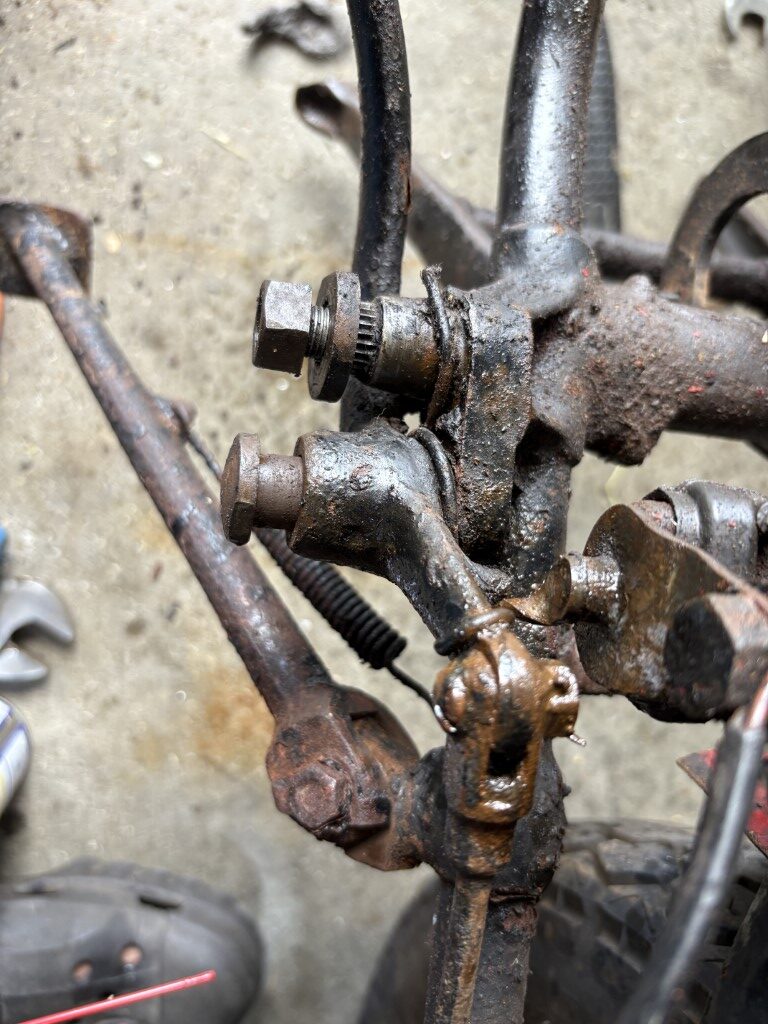
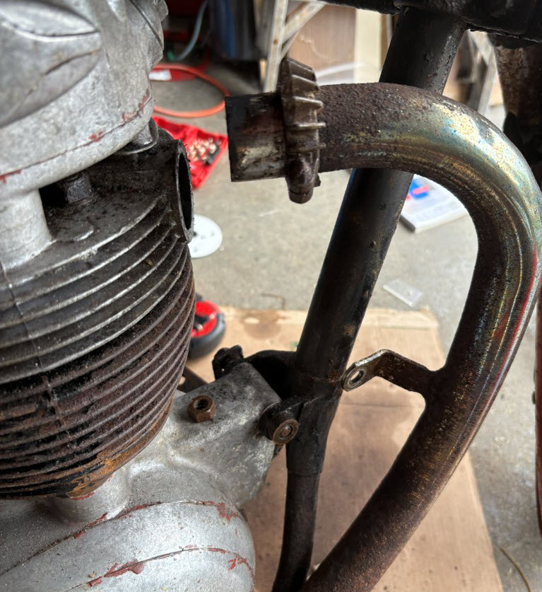
I was looking to remove the Nut at (E) which would allow the top part of the steering yoke to be removed vertically up (allowing (C) to also slide up and over), but after speaking with Douglas Jones his suggestion made the most sense.

The Handle Bars. Need to remove the brake and clutch handles.

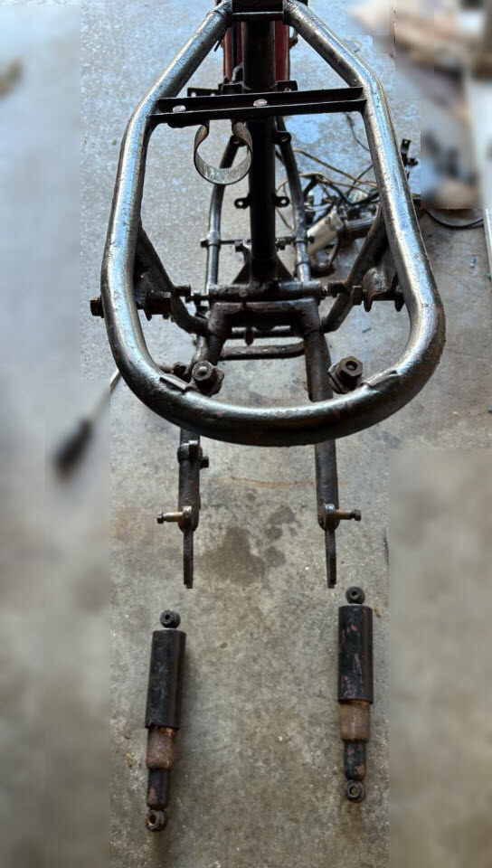
Per Doug’s suggestion I will take the nuts removed earlier from the tops of the tubes and use them to remove the suspension tubes. I will thread them back in down to the bottom and then back them out just 1 thread to keep maximum thread engagement. I can then use a piece of hardwood on top and pound them down (proper assembly support) to push them out of the taper wedge. This can be done for each and should help remove them from the assembly.

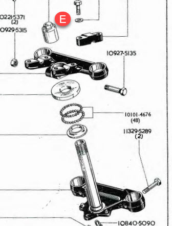
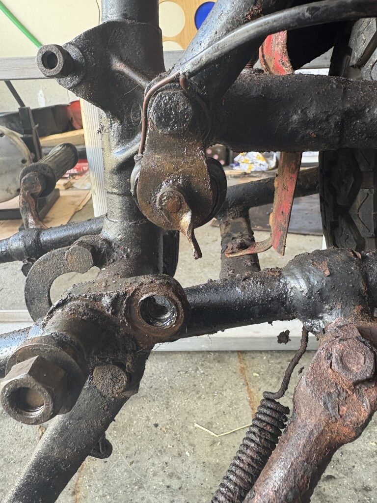
With the tubes out of the assembly the sheet metal (C) will slide down and leave (D) and (E) to be removed next.

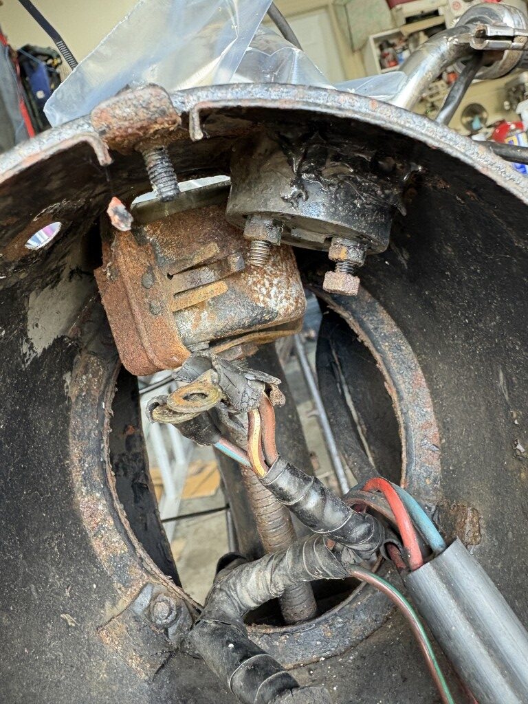
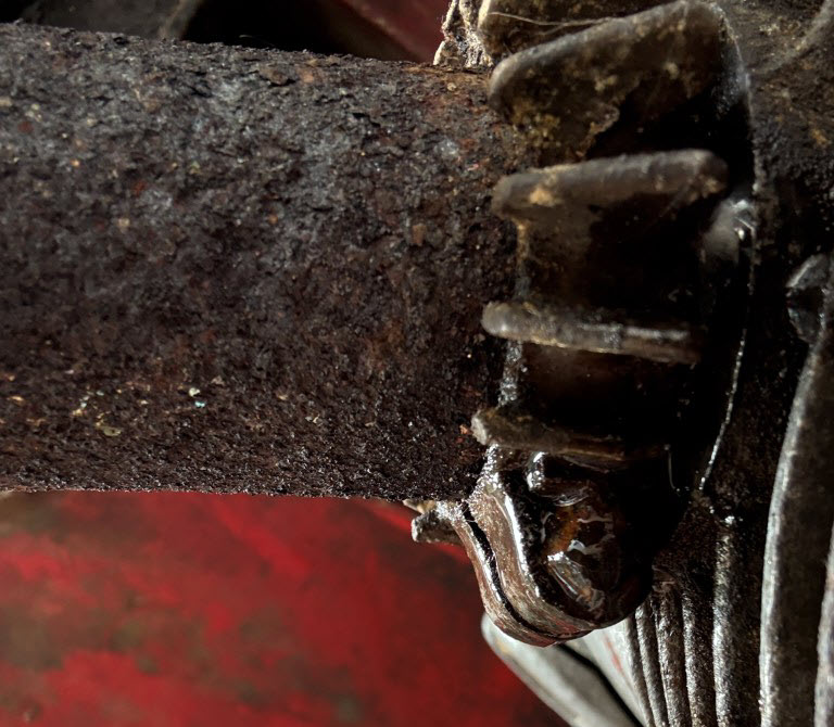
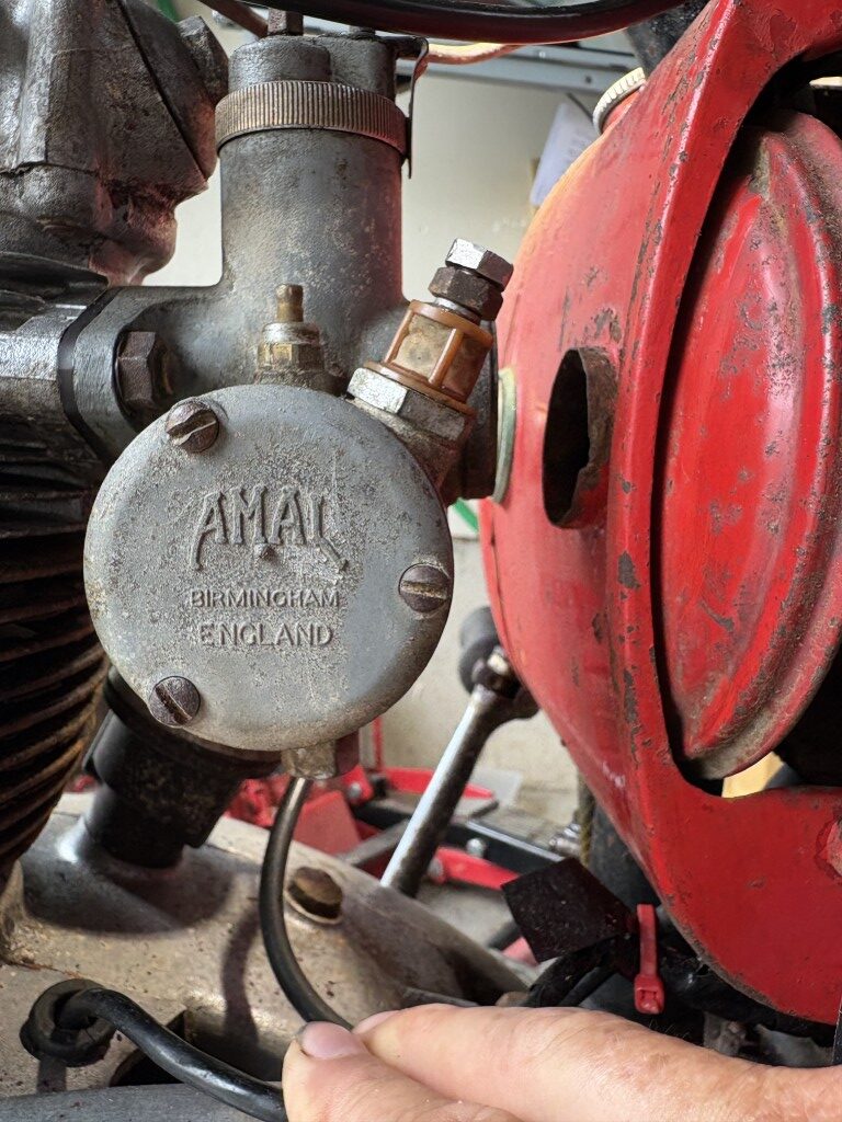
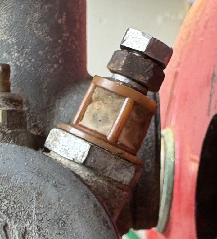
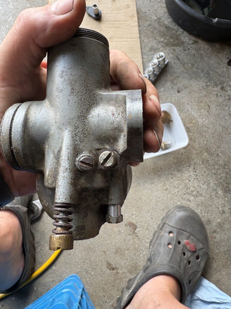
The nut (E) is now rounded and already the wrench was slipping. (some corner metal was left in Scotland) Will likely need to have help from the neighbor to weld a large nut onto the top of the component (E) so that my impact wrench can be used to release and disassemble the stem.

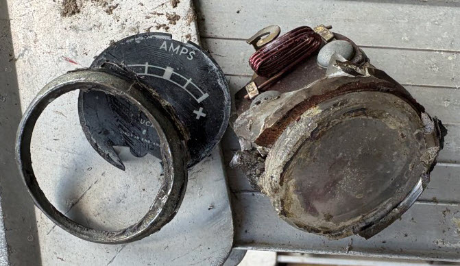
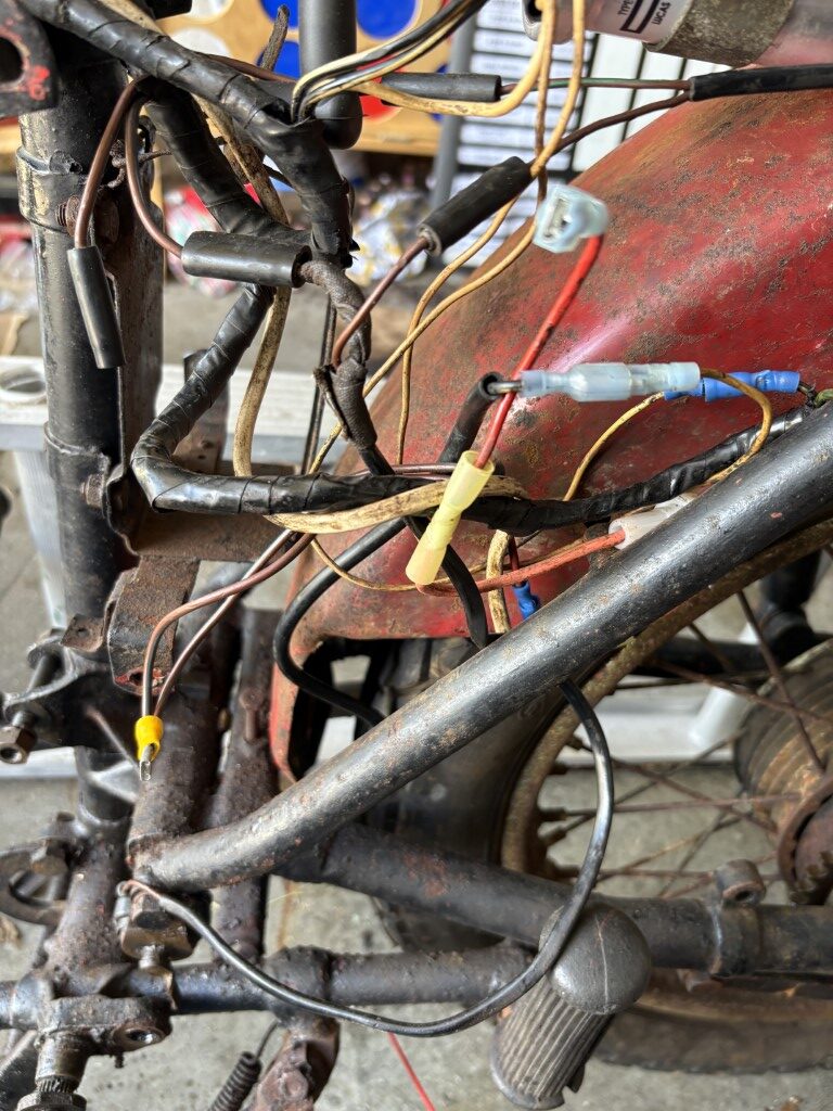
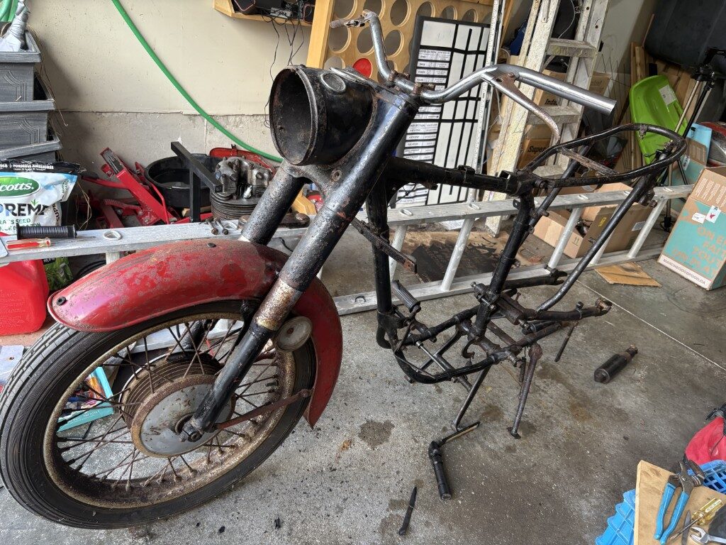
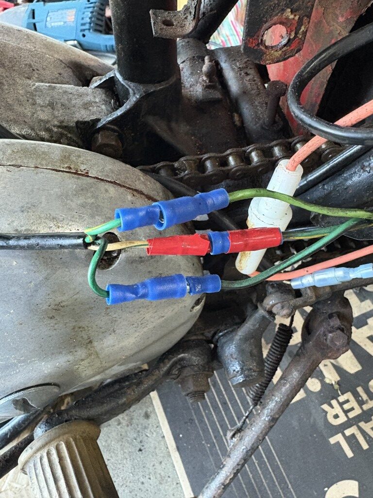
The Ammeter was in spot (C) of the headlamp but it was no longer electrically connected in the circuit (prior issues). The wires were all on one of the terminals, so I deduce that it was already causing some issues prior to storage. The unit was also put in using some type of Scottish goop. I hit it with the heat gun to create soft goop and for sure it started to peel away, but then within a few minutes the ammeter fell apart… guess it was also made of more plastic than I realized. Will be adding one of those to the shopping list :o)

The unit had 4 slot screws and nuts where (A) is shown above equally spaced around the inner ring. Had to get my neighbor over so that we had 4 hands. Two trying to keep the screw head from spinning and two to get the swivel socket on the inner nut and turn it to ultimately snap the bolts. I think all of them broke, but replacing them with small stainless steel nuts and bolts will be the repair.

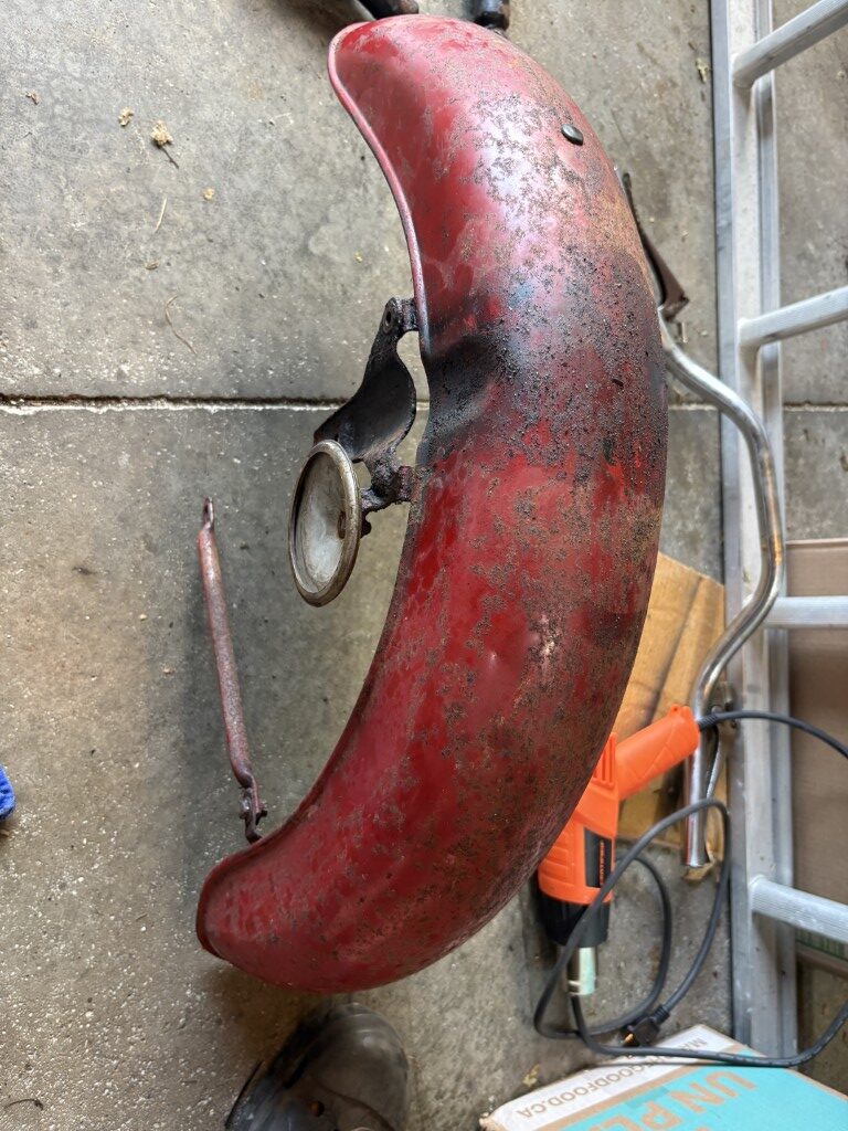
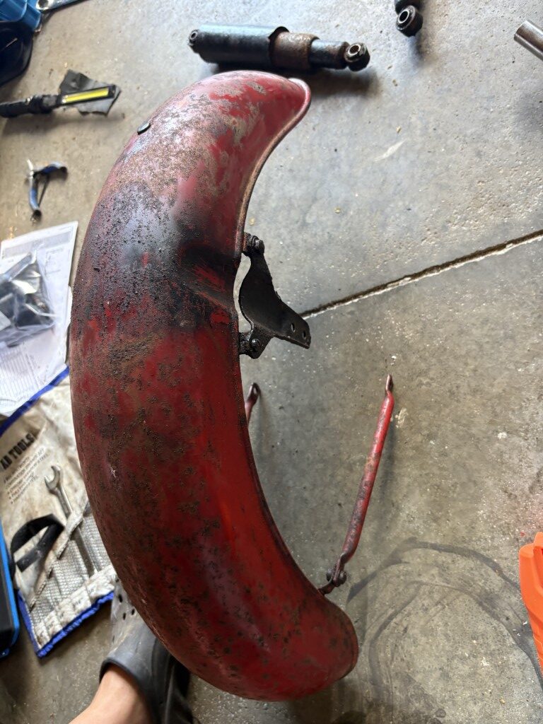
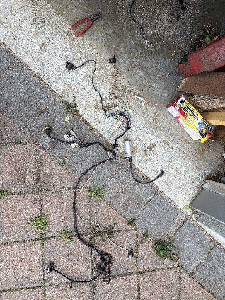
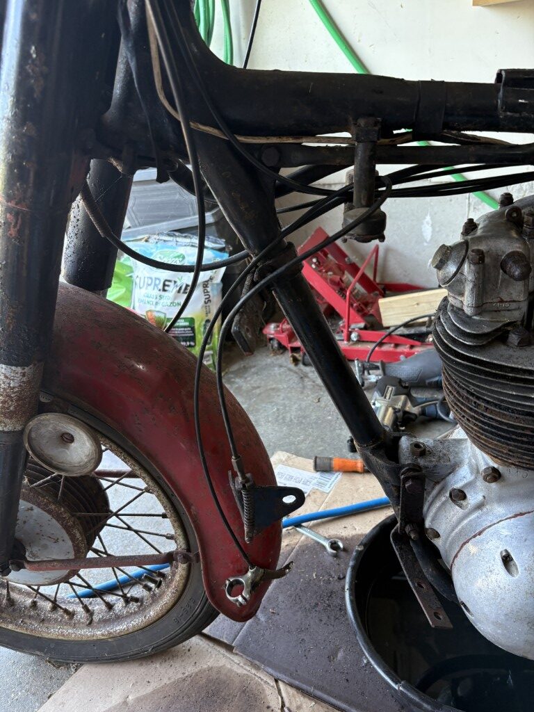
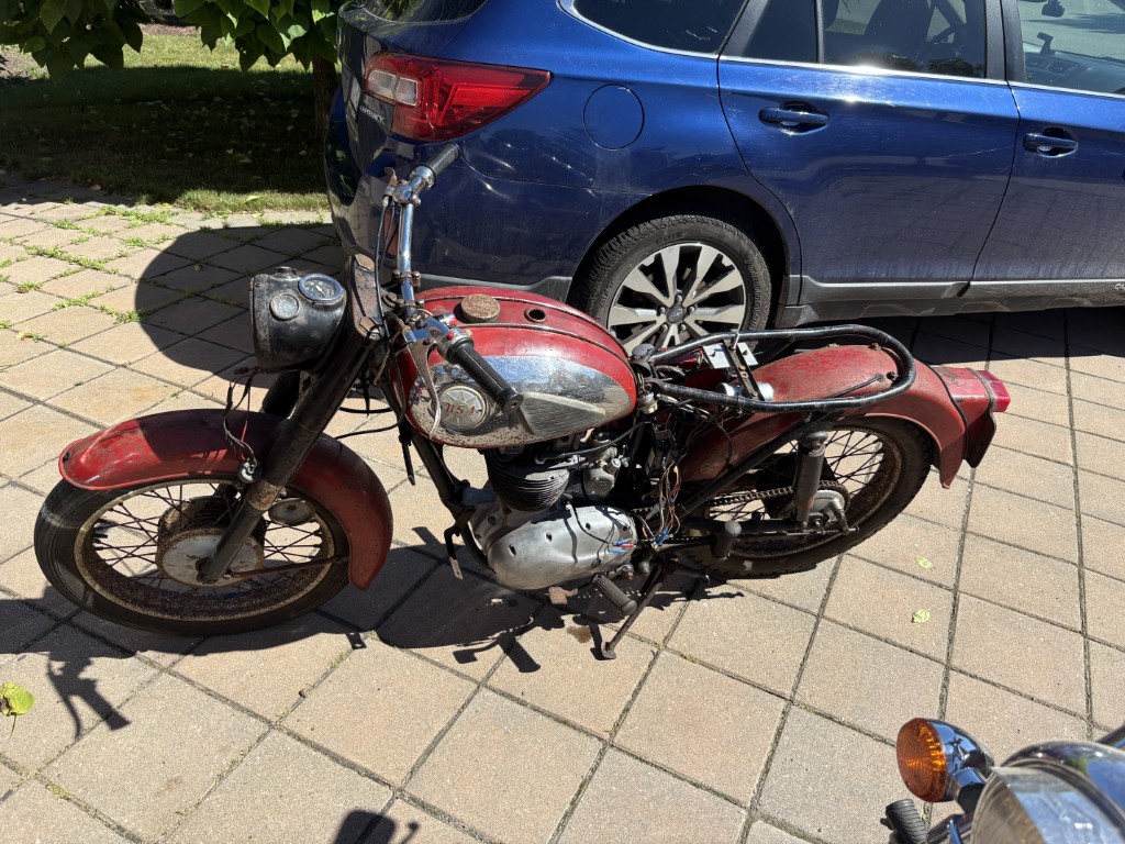
The front fender is removed and now just to remove the components before cleanup. those bolts might not survive the removal process, but are bound to be replaced in order to remove the 50+ years of rust and grime.

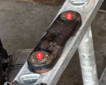
The state of the steering column lock nut above did make me aware that Willie had likely done some work to this area during his 10 years of riding fun.

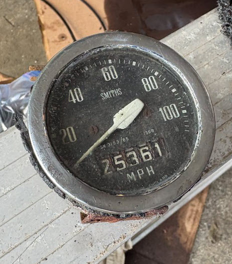
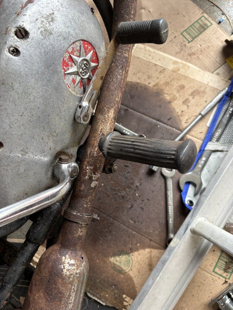
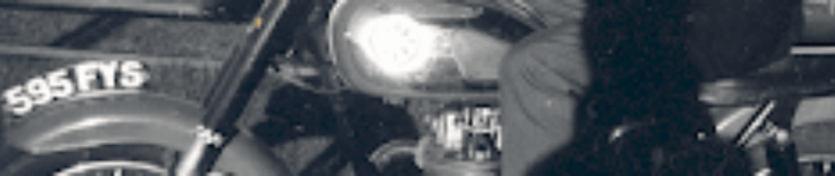
If the odometer is correct and accurate then 25361 Scottish miles was put on this bike which is around 2500 per year. Not bad in the Scottish summers :o)

Off for a CVMG Breakfast in Chatham ride tomorrow, so likely trying to get the suspension removed and the rest of the steering column disassembled tomorrow afternoon. Mario told me to be ready to catch the 48 ball bearings and in the past they would put some magnets around on the floor to help catch the balls. Not too hard to replace but will see if I can get a cardboard box underneath when we start separating the steering column.

Posted in Uncategorized | Leave a comment

Tear down – to the Frame!

Not sure I thought I’d get this far today, but here we are. I started today with the foot pegs and pedals as a goal. The right one (gear lever) is still attached—mainly because the bolt/nut is now perfectly round. Definitely on the replacement list. I even wondered if it was reverse thread (still trying to find out), but whichever way I tried, it just sneered at me. I’ll get later to the fact that the gear lever is on the right and the brake pedal is on the left.. total opposite from all our other bikes… hmmmm. Not sure why this just due to the left side driving, but here we are.. discovery.

The brake-side foot peg and lever were a bit kinder. The foot peg nut turned out to be reverse thread (thank heavens for small mercies). The brake pedal, though, came with its own bag of tricks. One wee nut had a cotter pin that had rusted in place—took more finesse than a Glaswegian trying to eat soup with chopsticks. There is also the brake-light switch which is going to need some love and attention.. wonder if it was working in the end… at first glance I’d guess not.

Next came the sheet metal that holds the battery and assorted bits, which of course led me straight into battle with the shock absorbers. Those, in turn, demanded the fender come off, which politely insisted that the rear wheel had to come off first. This BSA clearly has a sense of humour—every step feels like being told, “Aye, you could do that… but not until ye’ve done three other jobs first.”

Looks like a bit of a bees nest in there.. but it and the brackets all came out ok.

The upper bolts for the shocks were tighter than a Scotsman’s grip on his last pound note. Just when I was about to admit defeat, my neighbour wandered by. With the two of us and a hammer (the ultimate Scottish torque wrench), the shock absorber finally waved the white flag.

After that, I removed the wiring harness and then the electrics inside the headlight—the 1960s version of a modern fuse box, except with fewer safety standards and a lot more character. Grips and electrical connectors came off the bars to allow everything to snake through the headlamp.

Now the bike is rather bare (phew), stripped back to a skeleton. Next job is the front wheel and forks—but that’s a story for another day, once I’ve had a strong cup of tea (or perhaps a dram, depending on how the bolts behave).

Posted in Uncategorized | 2 Comments

B40 350 Engine out…. milestone (toes intact)

Hope it’s clear now how the engine stand works. The extended leg lets me lay the motor down on either side, which is handy for maintenance, or for when I just want it to think about what it’s done for the past 64 years. The top end is fully accessible, which is both exciting and mildly terrifying.

I still need to go get proper bolts and washers, but for now I’m using the frame bolts just to hold it in place. You know, the old “don’t worry, it’s temporary” approach — the same philosophy that keeps duct tape sales strong.

In the last photo, you’ll see the stand was not yet painted, but I did manage to install some Amazon.ca plastic plugs. Because nothing screams “professional restoration” like $4 worth of imported plastic caps.

The Removal Process (or: How to Test Your Friendships)

  1. Exhaust valve release cable: Removed from the top end. No drama here, which immediately made me suspicious.
  2. Oil feed lines: These deliver oil to the top valves and gravity drains it to the sump. I put hoses over the feed points with the nuts attached to keep out dirt. This was mostly successful, except for the bit where I got oil on my shirt anyway.
  3. Distributor wire: Disconnected, which means the bike can no longer spark — or judge me silently from the corner.
  4. Generator wires (3): Removed. These are responsible for charging the 6V battery and coil. I labeled them carefully to avoid future “why won’t it run?” meltdowns.
  5. Clutch cable: Still attached inside the right side, so I disconnected it at the lever and wrapped it around the top. Very professional. Definitely not what you’d call “farm-engineered.”
  6. Carburetor: Removed and covered with a precision-machined dust shield (aka a scrap of cardboard). NASA, eat your heart out.
  7. Kickstart lever & gear shift: Already removed earlier during the “exhaust pipe fiasco,” which you may recall was resolved with a Sawz-All.
  8. Engine mounts: Three bolts: front, rear (stud with two nuts), and cross bolt underneath. Each one removed without incident — which makes me think the engine knew what was coming and decided not to fight.

Extraction Team: Me + Neighbor

This was a two-man lift. We raised the front, lowered the rear, twisted the motor clockwise, tilted it right, rotated it 90 degrees, and finally set it down on cardboard. If it sounds like a complicated dance move, that’s because it was. I’m pretty sure we invented the “BSA Salsa.”

With the engine out, I wrestled it into the stand and bolted it in. Front bolt first, then rear. It now sits like some ancient relic on display — equal parts intimidating and oddly majestic.

The Plan

One of my friends from the CVMG London branch, Mario (because every restoration needs a Mario), has generously agreed to help me break the engine down and rebuild it. I’m confident it’ll run, since I had it running before disassembly. The clutch plates, however, appear to be fused together after a half-century of napping in a shed. I even tried the “kick it in gear while pulling the clutch” trick. The result? Nothing freed up, but I did get some excellent cardio.

Stay tuned — next chapter will likely feature me discovering what 60 years of British engineering looks like from the inside. Spoiler: probably oily.

Just got back from the weekly Saturday morning 9:30 coffee at McDonald’s, where the London branch of the CVMG convenes to drink caffeine, swap stories, and gently remind me that buying a 1961 BSA was a “life choice” I’ll be explaining for years. Everyone congratulated me on my milestone (translation: the engine is out and I’m still married) and then promptly volunteered me to create a flyer for the September Swap Meet. Apparently, I “look like someone who knows computers.” They asked, and for once I didn’t lie — though in hindsight, maybe I should have. I’m trading BSA knowledge with Mario for how to work his technology.

I missed all the early spring swap meets, but I’m catching the late ones with a shopping list that currently reads: Exhaust/Silencer, clutch bits, and possibly a therapist. There’s one on September 6th and another on the 28th, which should give me plenty of chances to buy rusty parts at premium prices and ask enough questions to risk a lifetime ban. Now the only challenge is convincing Holly to subcontract the flyer project before the club finds out my real design skills peak at “WordArt.” :o)

Posted in Engine | Leave a comment

Exhaust removal – Engine next…

Lets’ start with the death shot image to the left

Ok… so the exhaust is removed. At first glance it appears to be a success — but not the kind of victory I had in mind. I was picturing a clean, one-piece removal, like pulling a sword from a stone. Instead, it was more like digging up an ancient fossil with a jackhammer.

Sure, the pipe was so rusted it wasn’t going to win any beauty contests, but technically it was doing its job. It did function as a “silencer,” though in that very British way: it didn’t silence much, it just made the noise sound slightly more polite.

Now, here’s the fun bit: the pipe is held on in two places (A) and (B). The whole system is actually two pieces joined with one pipe sliding into the silencer, clamped at (C). Easy enough in theory. Except the section in the yellow box passes through the kickstarter, the foot peg, and the gear shift. Once everything was loose, you’d think the pipe would just slide out with a cheerful “pop.” Nope. Instead, it was like trying to solve a mechanical Rubik’s cube designed by someone who hates you.

Removing the foot peg should have made it possible. But of course, the bolt and nut had other plans. The foot peg bend blocked a socket, and a spanner? Useless. Too close to the ground, bad angle, no leverage. The open end managed to get on one set of flats, but with enough pressure it started rounding the corners. Arrgghh. At that point I summoned the pneumatic impact — my Excalibur — but all it did was create rounder nuts, inside and out. Almost heroic, but not quite.

Enter the Sawz-All. When 50+ years of engineering stubbornness meets modern reciprocating fury, there’s really no contest. Let’s call it: Engineers 0 – Sawz-All 1.

Oh, and the kickstart? That had its own little trick — a wedge piece pulled into the lever to hold it against the shaft. Over time, the pin had collected more dents than a bumper car, and it fought me every inch of the way. It’s now on the shopping list.

Finally, the exhaust pipe — slip fit into the cylinder, held with a bracket. I had a quick sanity check call with Mario (every restorer needs a “Mario”), who confirmed the finned ring casting was just a heat relief and could be removed later. Good to know I wasn’t about to dismantle something sacred.

Next up: engine removal.

If the exhaust was this much fun, you can only imagine what’s coming next…

Posted in Uncategorized | 2 Comments

Engine holder.. assembled!

Not bad for $10 in scrap steel with some left over.

This is what it looks like so far. My neighbor did the welding and it’s tricky to do the tack welds and then how to keep everything square and aligned as you fill the welds (heat warping the steel). The part on the left we made so it fits together with a joint so that it can be removed. It’s only required if you tip the assembly down to work on either side of the motor.

I spoke to one of the CVMG guys (mechanic) and he said back in the day they just put them in a wooden box (remove sides likely) as an engine holder. Of course not so easy to find a wooden box anymore as that was likely when vegetables came in them :o)

Next steps are to get some black rattle can paint and put a few coats on it with maybe a coat or two of clear coat… then I will put in the plastic plugs for the ends that I got from amazon,

I still have to measure and drill the holes to mount the engine before I do the pretty work and before it starts rusting…..

Posted in Uncategorized | 1 Comment

Engine Holder – Prep

Today I took the 6 pieces of 1″ square tubing purchased at a local metal shop for $9 and cut out the pieces required for the welded assembly.

Tool of the day was at my neighbors. I had a metal chop saw for a while, but sadly it was James’ and so it’s no longer in my Garage. I setup and measured all the pieces I’d need from the 6 24″ lengths of 1″ sq tube.

Neighbor setup a working table for me to measure and debur and you can see on the floor the finished pieces as well as some left-overs.

The last photo (without the book) is the assembly table where we’ll start to tack weld and assemble. Ended the day today with all pieces ready and marked for assembly. Tomorrow we (neighbor) welds.

Posted in Uncategorized | Leave a comment

Engine mount.. Fab begins…

The diagram is a rough sketch of the pending build. I obtained it in one of the initial books purchased for this journey. I’ll put later the more detailed version. Many dimensions missing, but since it’s a 1 to 5 scale I can measure from the book.

I’ll post pictures of the completed unit that my neighbor is going to assist as he’s a top notch retired welder and great metal fabricator.

I managed to pickup the 1″ square tubing from a local metal supply vendor on their cut-off rack. They happened to have 6 24″ lengths and this should allow me to complete the full assembly.

I had to clean the rust from the steel and the following 3M tool was recommended to use on my Power Drill (Milwaukee). Wow was it a good remover of the rust and likely left the surface close to ready for painting.

The full diagram of the assembly is below..

Posted in Engine, Uncategorized | Leave a comment

And with a kick….

After my first run with Bohdan pushing I worked on the carburetor a bit more. I had to rebuild it again as you might recall at the end of the road trial a major gas leak was noted. Luckily the gas valve from the Triumph worked very well.

I’ll post the video below so that people know it’s real 🙂

This was an accomplishment and I felt now that the bike is ready to start planning to strip down and truly restore.

Video filming by my neighbor Arnold

Posted in Engine | Leave a comment

Bubbling gas…

The gas was bubbling out of the “tickler” as it’s called. I had to fully disassemble the carburetor and clean some of the areas.

Mario gave me a tip to use some toothpaste on the tip of the old needle and twist it to assure it polished the seat for the new needle. After I did that and reassembled then there was no more leakage at the tickler.

I had already rebuilt the carburetor, but took it apart and after cleaning the needle seat I reassembled and no more tickler valve leak :o)

Posted in Uncategorized | Leave a comment

Push me Bohdan….

Kicking the bike was not working… I certainly had tried…

Even some other BSA owners had said that sometimes these bikes just tended to bump start better. I have bad memories though of bump-starts. Although over my years I’ve pushed many and been pushed I’d also left some victims behind of pushes gone wrong. Eleanor fell victim once in Brampton where her hands and upper body just went faster than her feet :o). Michael O’Neil was my saddest story as he bump started my bike for the last time as he was heading west (I was heading east). It was on a downhill and once the engine caught the bike just left him on a bit of a slop (while running). He feel forward and although his hands broke his fall… the fall broke his wrists. His journey that year was cut short and I’ve had to fight the guilt for years.

The following video was unfortunately captured on the second loop, so it was running pretty good. I also have a picture of all the rubber left on the driveway, but to be honest it started after the third push Bohdan provided. On my first pass I yelled for him to record the event (as I was scared running it too long might cause an issue).

Might have to try and crop or edit this video to center on the run. At the end we had stopped video ing the event, but when we looked down gas was pumping out of the carburetor, so glad we did not have a fire and I’ll post about that finding next.

Photos show the rubber marks on the driveway as we were bump starting the bike. I rode it with no seat but it was not too uncomfortable. Bohdan checking it out after the run.

Posted in Uncategorized | 2 Comments