A Wee Visit, a Broken Tool, and the Birth of Version 2.0
Took the Vulcan 900 out for a spin today — had to remind it that it’s still part of the family, even though the BSA’s been hogging all the attention lately. Ended up dropping by Mario’s to deliver a few bits of his I picked up from Walridge Motors. They’re close to me, so it made sense to bundle his order with mine (and also because I secretly enjoy pretending I’m doing something productive while out riding).
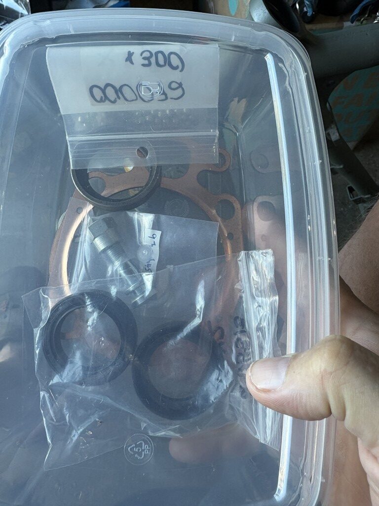
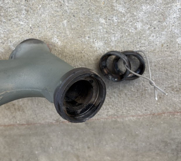
My treasures are tucked safely in the plastic tub — you can even spot the shiny copper gasket for the top end, and I’ve now got the fork seals ready to go. Just waiting on the elusive exhaust valve, and then we’ll plan the grand Top-End Assembly Day — ideally before the garage turns into a meat locker.
Now, about that rear shock… remember the “special tool” I made? Aye, the one that decided to self-destruct during round two. Turns out the nut had seized on the 3/8″ rod and I managed to twist it with my legendary brute strength (or maybe it was just bad design — but we’ll go with strength). The result: one mangled contraption and a lesson in humility.
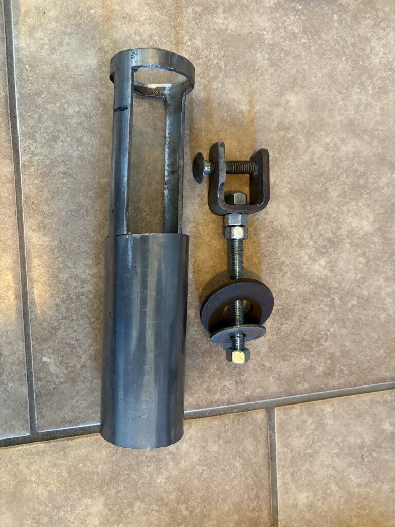
So, today’s task at Mario’s barn-garage was Version 2.0. Same tube, but this time we added a proper U-shaped end to grab both sides of the shock bushing instead of relying on that “it might work” setup from v1.0. Even managed to use real washers instead of a socket contraption — we’re getting fancy now.
And would you believe it — the collets actually popped out without a fight. No blood, no swearing, no new dents in the workbench. A success by any Scottish standard. Might weld the washer later or craft a proper endcap, but for now it’s holding up nicely.
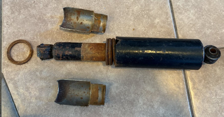
The shock is mostly disassembled — the spring slides out fine, and I’ll be giving it the full de-rust and repaint treatment.
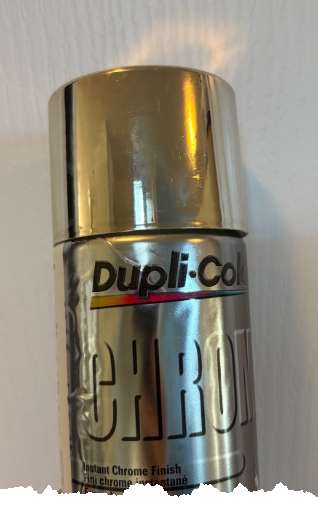
The plan is to paint the black bits black again (because that’s what normal people do), and for the shiny bits, I’m testing out Dupli-Color’s “Chrome-Like” paint. Sounds optimistic, doesn’t it? We’ll see if it’s more chrome-like or aluminum-foil-like once it dries.
Weather looks decent tomorrow, so I’m planning to set up my outdoor paint booth at the side of the house — using some leftover chipboard from the shipping container.
Nothing says “professional operation” like a backyard spray booth held together with hope and clamps.
Cold’s creeping in, so most work will soon move indoors — but for now, we’re still fighting the good fight in the garage, armed with coffee, optimism, and slightly improved tools.
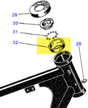
“The Goose Neck Ballet — Featuring Fire, Sweat, and Forty-Eight Little Devils”
Today was the grand occasion — the day the goose neck bearing races were to come out. Now, if you’ve never had the pleasure, the “goose neck” is that proud bit of the frame where the steering forks pass through — the backbone of the beast. On top and bottom, you’ll find bearings. In the B40’s infinite wisdom, these aren’t modern, civilized caged bearings — oh no — they’re 48 free-range, unrestrained little ball bearings rolling wherever they please (they bounced around my floor when removed earlier and .
This image helps to understand the Goose Neck reference.
Upon earlier disassembly, I found the races inside the frame looking like the surface of the moon — pitted, scarred, and most definitely past their best-before date. I was also short two of the 48 balls, which I can only assume gave up sometime in the last 55 years, vaporized into bearing dust, and helped carve out those pits as a parting gift.
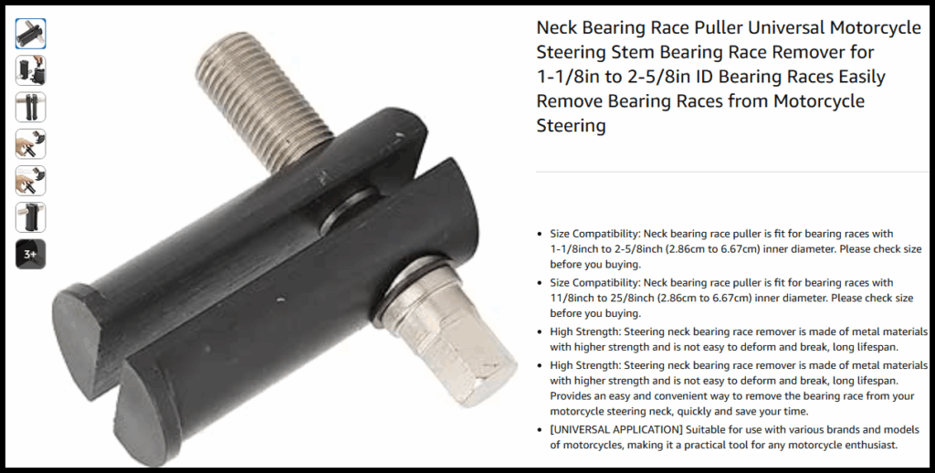
Now, before I got too medieval on the goose neck, I did what any sensible person would do — I bought the proper tool. A tidy little contraption that expands behind the bearing race, letting you drive it out with a drift — clean, precise, professional. About twenty bucks well spent… or so I thought.
The idea is simple enough: keep the race coming out straight so as not to gouge or kink the bore. Easy to say, harder to do when everything’s tighter than a Scotsman’s wallet on payday. I found out there was no lip to hook on and so back to the blank canvas.
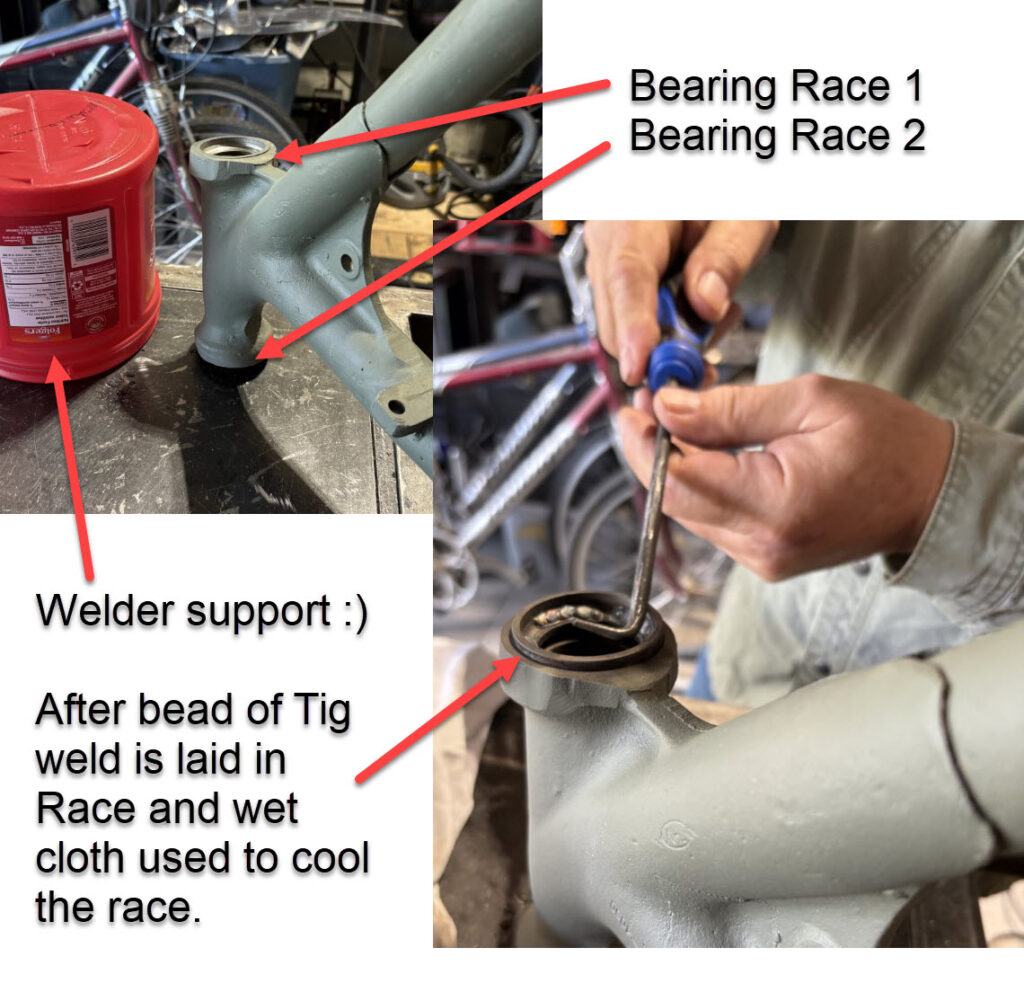
So there I was at our usual Saturday CVMG coffee meet at McDonald’s, lamenting my wasted $20 investment, when one of the lads pipes up and says, “Why bother with that fancy gadget? Just throw four wee spots of weld on the race — when it cools, it’ll practically fall out.”
Aye, right.
Apparently, this is a known method, backed by the collective wisdom of several gents who’ve done it “loads of times.” I’d even seen a reference video (see my previous post), so the theory was sound — in that “what could possibly go wrong with welding near your frame neck?” kind of way.
Still, the peer pressure of McDonald’s coffee club is strong. And if a bunch of vintage bike lads say it works, well, how could it possibly go sideways?
No Video, but a few action shots of the proecess. The Red tub is for arm support to assure No video evidence of the operation (probably for the best), but there are a few action shots from the scene. The red tub in the photo wasn’t a random prop — that was my improvised armrest, there to steady the hand and make sure the weld only went on the race, not into the frame.
Precision, you see.
In the photo, you can make out the weld bead — two or three neat little spots — and after a quick chill-down with a very wet rag, the race obediently loosened its grip. A small screwdriver and a pick did the rest. Out it came, smooth as you please.
A huge thanks to my neighbour Steve — a retired pro welder who wisely gave a verbal NDA to assure he was not to be implicated if it went wrong.
As for the mysterious red patch in one of the shots — I wondered about that myself. Turns out the melting point of a plastic coffee tub is somewhat lower than that of mild steel. My “precision arm support” sagged into early retirement, a small sacrifice to the gods of backyard engineering.
But the proof’s in the pudding — both races now out, no frame damage, and just a wee bit of touch-up needed on the primer. Mission accomplished, with only minor collateral damage and one less coffee tub in the world.
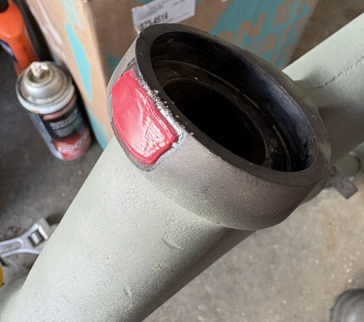
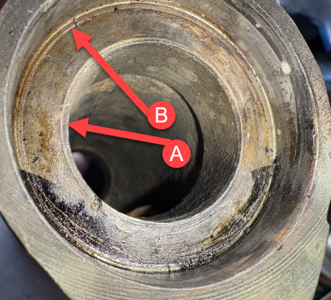
Interesting:
So there you have it — a zoomed-in mystery worthy of a detective. At first glance, (A) looked like a sleeve pressed in, but after some squinting, pondering, and a fair bit of muttering, it appears (A) and (B) might actually be a relief cut — likely done to ensure the bearing race sits perfectly square, top to bottom. A small detail, but exactly the sort of thing that keeps a restorer awake at night, wondering what the lads at BSA were thinking back in the day.
Next step: taking inventory of all the parts on order. I’ll soon be diving into the engine top end, and once the frame’s painted, the rebuild can finally begin. The real fun is about to start — assuming, of course, nothing else decides to “fall out” in the meantime.
Stay tuned — the next act in this ongoing BSA resurrection promises fewer weld burns, fewer missing ball bearings, and (hopefully) fewer melted coffee tubs. But no guarantees.
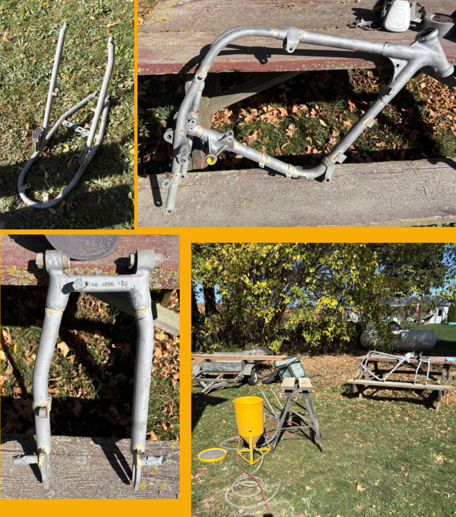
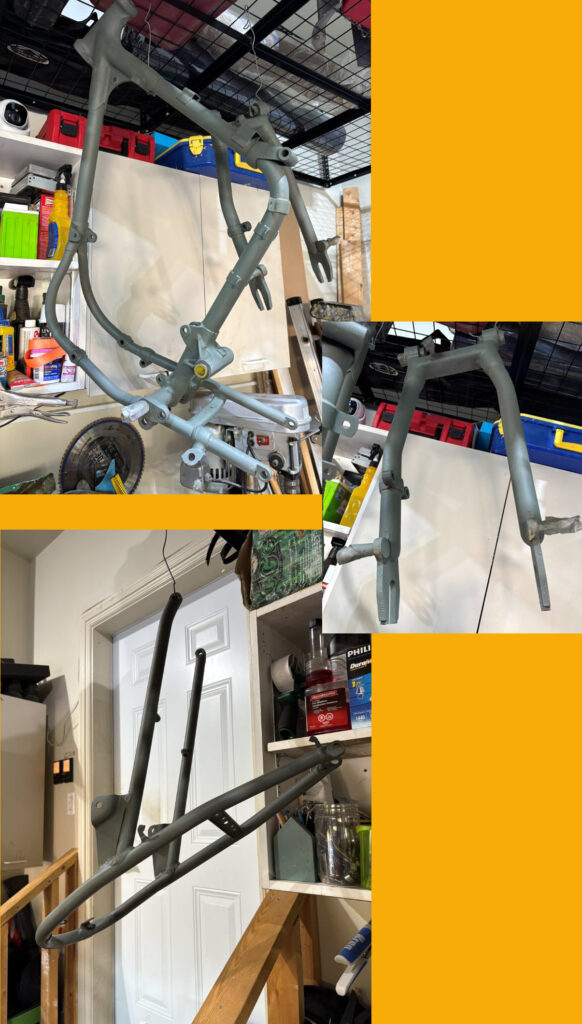
I had a wee bit of choice when it came to the frame. Earlier on, I’d broken it down into its three main bits — the front loop, rear section, and swing arm. One tempting option was to have it sandblasted and powder coated. I even got a quote for about $300. Not bad, but that’s a fair few pints of Guinness or a new set of gaskets, depending on your priorities. DIY saves money.
A few of my CVMG pals, always eager to offer “advice” (especially when it’s not their back doing the sanding), suggested I save the cash and just rattle-can it myself. “It’s mostly hidden when the bike’s together anyway,” they said — aye, the same logic used when choosing socks for a kilt.
And they’ve got a point — once the tank, engine, and wheels are back on, the frame’s about as visible as a haggis in the Highlands. But powder coat has its downside too: once it chips, you can’t just touch it up without it looking like a bad paint job on a pub wall.
At one of our CVMG meetings, I had a good blether with Bruce. He told me about his garage setup — and I swear it sounded like the Rolls-Royce of sheds. He’d just installed a two-stage compressor that could probably power a small jet, never mind a sandblaster.
Bruce’s done his own painting before and was generous with the tips — the man’s clearly sprayed more things than a Scottish midge in summer. Better yet, he offered to let me use his setup to sandblast my frame. After a bit of calendar juggling, I made the trip out to Thorndale last week, where I also picked up some primer he recommended from a local shop.
So now the plan’s set — the frame’s getting the DIY treatment. Let’s hope by the end it looks more “classic restoration” than “crime scene cleanup.”
Blasting Away – The Frame Gets a Proper Scrub
Below you can see the finished pieces — or as I like to call them, the “shiny survivors.” I went through a full 50-pound bag of glass bead and even dipped into a wee bit of Bruce’s stash to top up the hopper. (Aye, he caught me red-handed, but I told him it was for the good of British engineering.)
You can spot the setup in the lower right of the photo — a proper DIY sandblasting station on the trusty Workmate bench. By the time I was done, the top of that poor bench was cleaner than a freshly shaved Scotsman on wedding day.
The results were brilliant — the paint practically lept off the frame, and the brazing welds came through like gold veins in a miner’s dream. I’d plugged all the important holes and taped the threaded bits with duct tape (as any true craftsman would).
By the end of the day, I was covered head to toe in dust, deaf from the compressor, and grinning like a loon. But aye — this day was a grand success! Glass kept raining from my hair each time I scratched an itch.
Paint Like Ye Mean It
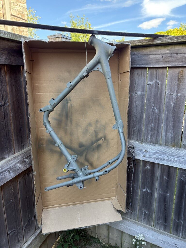
Next up, I cobbled together a state-of-the-art paint booth — right outside the garage, tucked neatly in the corner by the fence. A hockey stick served as my parts hanger (because this is Canada, after all), and I nailed a cardboard box to the fence to catch overspray. The neighbors must’ve thought I was either painting a masterpiece or opening a back-alley repair shop.
To my surprise — or perhaps against all odds — it actually worked a treat! With just one rattle can, I managed two coats, and they turned out rather decent (In My Own Humble Opinion, which of course is the only one that matters – next to E’s).
Now I’m convinced I can build a proper version of this “booth,” maybe even with walls that aren’t flapping in the wind. I’ll be spraying the frame in black next, with a few layers of clear to make it shine like a freshly polished sporran.
Aye, the future’s bright — brighter than the paint, even.
The Battle of the Bearing Races
Before I can get too carried away with paint and glory, there’s still the small matter of those blasted bearing races hiding up in the goose neck. They’re seated in there tighter than a miser’s wallet on payday. The inside diameter of the neck is smaller than the races themselves, so there’s no handy lip or edge to catch with a drift or puller — just smooth steel mocking me.
The plan? I’m teaming up with my neighbor to try the “welder trick” — a fine bit of mechanical sorcery where you run a bead around the inside of the race so it contracts and practically falls out. Or so the legends say. A couple of the CVMG lads swear by it, though they also said Triumphs don’t leak oil, so I’m taking it with a pinch of salt.
If all goes well, the races will drop out nicely, and if not, well… there might be some colorful language echoing down the street. Either way, it’s the next step before paint — and with a wee bit of luck (and maybe a fire extinguisher nearby), we’ll get it done. How To: Remove bearings with a welder
Aye, the primer’s on — and while it didn’t look like it covered perfectly in the photos, trust me, it’s consistent. (That’s my story, and I’m sticking to it.) The finish feels smooth, no bare patches, and everything’s sealed up nicely for the next stage.
I’m actually quite chuffed with how it turned out. The rattle can behaved itself for once, and I managed not to coat half the fence in green mist. Now I’m just waiting for a stretch of good weather to hit it with the black.
The plan calls for low humidity — which, judging by the last few weeks, shouldn’t be too hard to come by — and little to no wind. Nothing ruins a paint job like Mother Nature deciding it’s time for a dust storm. With a bit of luck, and maybe a calm day or two, I’ll finally get that lovely black finish on and follow up with a few coats of clear for good measure.
A Wee Bit of Sandblasting… Sort Of
I like to call it “sandblasting,” though technically I was using glass beads — but let’s not split hairs, eh? Same satisfying racket either way.
Next on the list are some nuts and bolts on the sheet metal that need to come off. A few will get the polite treatment, and the rest… well, that’s what grinders and nut splitters are for. Once the hardware is out of the way, it will be time for the wire wheel — a proper bit of elbow grease to get everything ready for paint. Nothing like a bit of steel-on-steel action to make a man feel alive.
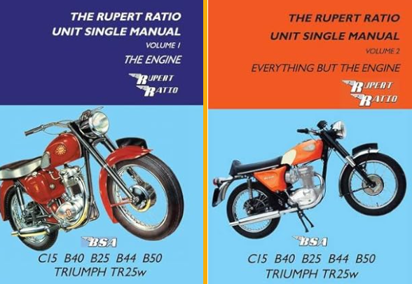
Bit of Back-story: Over Christmas, I treated myself to a pair of Rupert’s books — one for the engine, and one for everything but the engine. (Because why make things easy and put it all in one?) They’ve been brilliant references for my B40 project, and I’ve even exchanged a few emails with the man’s team. A fine chap named Dave Smith replied with extra details — clearly the poor soul assigned to deal with daft questions from folks like me.
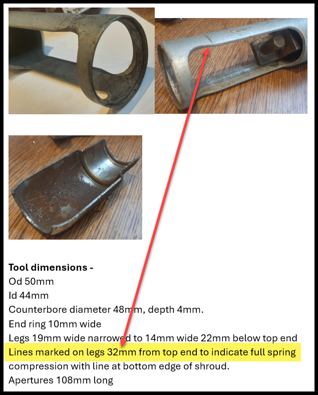
I’d reached out for more info on the tool used for dismantling the rear shocks — specifically, the one meant to remove the chrome collets. Mine, naturally, wasn’t working. (Because why would it?) I just wanted to confirm a few basic dimensions, but Dave went above and beyond — sent photos, measurements, and probably wondered how someone could overthink a spring compressor quite this much.
Screen shot of email body sent to me
The magic number, as it turns out, was 32 mm — that’s the proper compression point for the spring, or so the gospel according to Rupert says. I can’t say for certain, but I reckon I convinced myself it was fully compressed somewhere around 24 to 25 mm — optimism is a powerful tool, after all.
Thursday afternoon found me over at Mario’s, where the two of us gave it a proper go. With a bit more persuasion (and a few creative words), we edged closer to the 32 mm mark I’d scratched on my tool. Somewhere between 30 and 32 mm, one of the chrome collets finally surrendered — followed shortly after by the second, with just one more encouraging turn.
As for that minor counterbore some folks swear by — I’m fairly certain it serves no real purpose except to waste a bit of time and metal. I skipped it entirely, and my tool worked just fine, thank you very much.
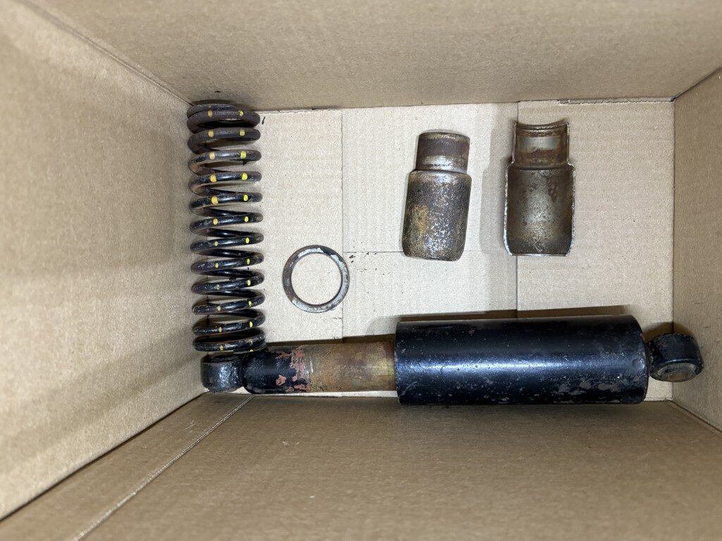
The shock assembly (in all its glorious pieces) is shown to the left, and I can finally get on with cleaning it up. I gave the hydraulic portion a few test strokes — purely scientific, of course — and it seems to be working fine, no oil leaks in sight. The seals aren’t replaceable, but let’s be honest, at this age I’m barely replaceable either.
Now comes the great debate: do I settle for a good cleanup and maybe a bit of nickel plating to make them look respectable again, or do I fork out roughly $175 for a shiny new pair? My wallet says “polish it,” but my pride says “treat yourself.” We’ll see which one wins — odds are, it’ll be the cheaper voice in my head.
And on that triumphant note — naturally, the universe had to balance things out. My trusty compression tool decided to retire early, failing spectacularly while I tried to tackle the next shock. Aye, nothing says “progress” quite like ending the day with a pile of parts and a broken tool.
So, it’s back to the drawing board (and the grinder) to rebuild the compression assembly — stronger, smarter, and hopefully daft-proof this time. Until then, the last shock will just have to sit there looking smug.
Stay tuned — because if history’s any guide, the next update will feature either triumph or more swearing… possibly both.
The above is the parts diagram for the front forks. Getting the oil seal housing to unthread from the oil tube was the real battle. It needed a proper “special tool” to engage with the internal nut and twist it free. So I made one—because clearly BSA thought I’d have a full machine shop hidden in my garage. Files, grinding wheels and a hacksaw maybe.
Today was the day. I clamped the sliding tube in the vise so the welded nuts stopped it from spinning, slid the tool into place, and gave it a heave with my trusty plumber’s pipe wrench. With a creak, a groan, and maybe a few muttered words my grandmother wouldn’t approve of—it finally broke free. A wee victory!
Ideally, the tool would have a neat little T-handle welded on top. But in my case? The pipe wrench was my kilted Highland dance partner for the day. Functional if not elegant.
The second fork was a bit more stubborn. No surprise there—like brothers, one’s always more difficult than the other. I wandered over to the neighbour’s with it, applied a bit of gentle heat (translation: persuaded it with fire), and with some extra persuasion it finally let go. Another win.
With the circlip removed, the shot slid right out of the sliding tube. Off came the nut at the end, followed by bushings, shims, clip ring, and the oil seal housing. It all came apart like haggis at a Burns supper—messy, but satisfying.
Now all the parts are laid out in their own boxes, ready for inspection. New seals will be a must, but the rest will get a thorough cleaning before deciding what’s salvageable.
New seals will be a must, so two can be ordered right away. The rest will get a proper cleaning and close inspection before I decide what’s fit for service and what’s headed for the bin.
At least nothing went flying across the garage today—so I’ll call that Scottish progress.
This image shows the Donnybrook Legion, where the London Branch Swap Meet was held. Plenty of parking was available—though it filled up quickly at times, the turnover kept things manageable. With the Legion open and the sun shining, it turned out to be a great day for the event.
Here’s a look down one of the aisles inside. The weather was fantastic, and between the traffic in the parking lot and the groups gathered to socialize, there was a lively atmosphere all around.
I went in hoping to track down some key parts, but British bike components were in short supply this year. Still, I did make a promising connection—someone who may have a set of WM2-18 rims with good chrome for my BSA. He didn’t have them with him, but I’ll be giving him a call to arrange a trip out to Wyoming, Ontario (about 45 minutes away). He mentioned one rim has excellent chrome. They’re rear wheels, and I’ll need to confirm if the hubs are the same as mine. Fortunately, I really only need the rims; I can clean up my hubs and rebuild with stainless steel spokes (about $80 a set). It’ll all depend on the price he’s asking. For comparison, Italian chrome rims run about $150, while English chrome sets are closer to $250. Are the English ones shinier? Maybe—but unless they sparkle like the Crown Jewels, I think I can live with Italian.
A friend also reminded me to inspect my hubs carefully—specifically the brake drums. If the drums have been machined oversize, that could be a real problem during inspection. Since I don’t know the full history of the wheels, I’ll need to check the specs carefully. It’s a bigger concern for the front hub since the drum is integral, whereas the rear uses a separate bolt-on drum. Looks like I’ll be hunting down the factory spec for a ’61 BSA B40.
One unexpected bonus: Dave Gibson kindly donated a spare B40 head he had sitting on a shelf. My current head needs a fin repaired and has a stud that must be reset, so having a spare gives me some peace of mind. Mario and I still intend to reuse the original, but having a backup eases some of the risk.
Outside of bikes, the weekend was a bit busy as well. My wife and I drove my mother-in-law back to Toronto for her flight to Scotland. She’s gone for till the next visit (2.5 weeks went quick), which means the household will be noticeably quieter—although I’m sure when she gets there, Glasgow will be complaining about the increased noise levels! On the way back we picked up a little 4×4 trailer I’d left with a friend for hauling landscape materials. It also is crying for attention as I hadn’t seen it in 4+ years.
Now that that’s sorted, I can focus on the next tasks: building tools for the front and rear shocks, arranging that trip to Wyoming for the rims, and hopefully getting access to a friend’s sandblaster to prep the frame and sheet metal for paint. Plenty to keep me busy—though as my Scottish relatives would say, “that’ll keep ye oot o’ the pub, laddie.”
At the end of the day, this project isn’t just about chrome and torque specs — it’s about carrying a bit of family history forward on two wheels. So even if the next post finds me with more excuses than progress, just remember: like a proper heirloom, this BSA rebuild will take patience, persistence… and probably a pint or two along the way.
So tonight was the night for preparing the new home of the piston and finalizing the decision on the rings, we’d a plan to meet at Mario’s garage for 3:30 sharp. Sharp, that is, if you go by Mario time — so naturally we got started closer to 4.
As Mario’s apprentice (read: gopher with delusions of engineering), I was on the tools and too covered in oil to take many action photos. You’ll have to make do with my rambling explanation.
The cylinder you see in the photo was already dressed up with three of the four bolts we were after (5/16″). The fourth one was still playing hard to get in the great junkyard of odd nuts and bolts Mario’s been hoarding since about 1974. He eventually fished one out and gave it a quick spa day on the wire wheel.
We were still rummaging through Mario’s treasure chest of doom — decades’ worth of orphaned bolts and nuts that looked like they’d survived at least two world wars. We’d managed to wrangle three that fit, and Mario had the fourth candidate spinning on the wire wheel, giving it a polish like he was preparing it for Sunday Mass.
According to the holy writ (the Workshop Manual), the head bolts are meant to be tightened down to 26 ft.lbs. The idea was to clamp the head onto the cylinder at that same spec, so the whole lot would behave like it was under proper working conditions before we started in with the hone.
But before all that, we did a wee science experiment with some long, delicate shims — each with a hole at one end so I could hang them off a scale. The numbers were something like: 1 kilo of pull with .004″, and about 2.5 to 3 kilo with .005″. In plain English: it proved the piston fit wasn’t a disaster. With the shim in place, we slid the piston up and down to check the gap stayed even across the stroke. It did — more or less — so we declared it “good enough to keep the piston from falling out,” and carried on.
Straight from the gospel according to BSA — the Workshop Manual for the Single Units — comes the holy word on what the ring gap ought to be.
We squared the rings neatly in the cylinder, poked in the feeler gauges, and had ourselves a measure. The verdict? About .028″. In other words: wider than a Scotsman’s wallet on payday. Clearly the rings have seen some miles, though who knows how many or when they first went in.
Rather than gamble, I’ve decided to order a set of +.040 rings from the UK. If they turn up and the gap’s too tight, we’ll break out the files and call it “precision fitting.” That’s the polite workshop phrase for what’s essentially fettling until the parts behave.
The photos above show our setup for the next step: clamping the cylinder in the vise with aluminium plates, then lining up the hone for its big moment. No video evidence exists — probably for the best — as Mario took on the role of oil-sprayer-in-chief while I manned the drill like a lad trying not to butcher his first woodworking project. Under his direction I eased the hone in and out of the cylinder, the goal being to smooth away the old marks and give the walls that lovely even crosshatch finish. By some miracle, it worked, and we were both chuffed with the result.
That wrapped up our afternoon’s graft. I broke everything down, released the cylinder from its compression bolts, and packed up the kit. Next step: rings on order from the UK and a patient wait for the postman. Until then, I gave the cylinder walls a good oiling back home — like tucking the old girl in with a blanket until she’s ready for the next round.
Lastly, we had a look at the pipes I’d brought along for the front fork tool. At first it was a hopeless fit — like trying to squeeze a haggis into a teacup. But Mario, sharp-eyed as ever, spotted a raised weld seam inside the pipe. A quick trim to length and a bit of filing later, and suddenly it slid on like it had been made for the job. Magic.
The rest of the fabrication is now officially my homework — let’s just hope I don’t cock it up when left unsupervised.
On Saturday we’ve got the first gathering of the newly revived BSA Owners group under the CVMG banner, and Sunday is the last swap meet of the season. Fingers, toes, and maybe even spanners crossed that I turn up some good finds before the snow starts flying.
Decided before I get back to being a tool-maker I would get some prep on the engine parts as I’m likely off to see Mario (the wizard) on Thursday to confirm some measurements and our plan for the rings.
To the left is the Rocker cover and how now the studs are all removed and for the most part documented and cleaned up.
Still need to give it a good wash and degrease as there is a chip out of one of the fins that my neighbor feels he can repair.
To the left is the chip from one of the fins… I’m sure there is a tool dropping from height story to go with this one…
Latest purchase of parts from Walridge for the motor rebuild. Still a few on backorder, but building my readiness kit.
Bottom right corner is a kit of stainless steel hex head bolts to replace the
Monday/Tuesday took me in different directions, but back to the tools and tasks tomorrow and off to see Mario on Thursday…
With the engine now containerized like some dodgy artifact in a museum, it’s my turn to review the pile of bits and start plotting the grand rebuild. First order of business: order the parts we think we know need replacing—because nothing says “confidence” like putting quotation marks around the word know—and then begin the glamorous job of cleaning decades of grime.
Some of the parts are on backorder, of course, but only 2–3 weeks. Which, in the world of vintage motorcycle restoration, is practically same-day delivery. Either way, they’ll arrive well before reassembly—assuming I don’t lose half the bolts down the garage floor cracks first.
Piston Rings
I wish my Father-in-Law was still around to fill me in on the “stories.” Funny how time slips by and it’s the little details you miss—the daft repairs, the shortcuts, the why on earth did you do that? I’m left piecing it together like some forensic mechanic, reading the tool marks and spotting the non-standard bodges. The piston, for instance, was definitely swapped at some point. Back in the early ’60s, that was no big deal—most bike owners knew how to change pistons and rings. Getting more than 30,000 miles out of one was pure fantasy. These days, engines happily chug past 100K, and most owners think “maintenance” means changing a lightbulb or trading the whole bike in for a shinier one. The art’s been lost, along with the smell of burnt oil baked into your fingernails.
Here’s Mario checking the piston-to-cylinder gap with a set of shims. We could squeeze the piston in with 0.003″, but it refused to slide through. At 0.005″ it was just loose enough to remind us we weren’t working with Swiss watches. That gave us our working range.
The plan now is to hone and clean the cylinder, which, of course, will probably nudge the gap a little wider. Nothing like a bit of suspense to keep the rebuild exciting.
And this is where the “science” (or, more accurately, years of stubborn trial and error) begins—with the rings. The piston is a +020, the first step up from factory STD. Back in the day, BSA gave you STD, +020, and +040, before politely suggesting you re-sleeve and start again at STD. Since this engine was running well enough before, this is really more of a maintenance check, made necessary by the 55+ years it spent sulking in a shed. The cylinder only needed a light deglaze/hone, and the piston itself was still in good nick. But either way, there was no way we’d reuse the old rings—they’ve had their day.
This piston has three grooves: the top two take identical rings, and the lower one is for the “oiler,” complete with a dainty little spacer. (See linked piston image for your daily dose of vintage metallurgy. – My piston diagram)
The rings, in case you missed piston school, do two very simple but life-saving jobs: they dump excess heat into the cylinder wall (since this engine is air-cooled and couldn’t chill a pint if it tried), and they keep combustion gases from sneaking past the piston like freeloaders at a football match. Trouble is, metal isn’t really solid—at least not when it’s getting roasted alive—so you have to allow for expansion between “sitting pretty” and “running like hell.” That gap will close up as the engine heats, and if you don’t leave one, the ring ends will crash into each other, buckle up or down, and shove against the ring lands. I’ve seen the aftermath: entire pistons turned into confetti. The last thing an engine wants is chunks of feral metal bouncing about in the combustion chamber.
So, instead of +020 rings (which might leave us with a comedy-sized gap), Mario suggests we go with +040 rings and file them down to fit. Custom job. His rule of thumb is about 0.002″ per inch of bore diameter. The ring manufacturers, naturally, insist on 0.004″ per inch. Who’s right? Neither, both, and somewhere in-between. Like most things with these bikes, it’s a cocktail of theory, trial and error, and the grumpy wisdom of mechanics who’ve been at it since the ’60s.
For now, I’m holding off on ordering the rings until we’ve cleaned and honed the cylinder, so we can actually get accurate measurements instead of guessing and praying.
To the left, you’ll see the clutch pressure plate—posed with four driving plates stacked up like pancakes and five driven plates sulking in the background.
I gave the driven plates a spa day with some very fine 140-grit sandpaper, just enough to scrape off 55+ years of fossilized muck. The driving plates still need their cork thickness checked, but at a glance they look fine—like they could actually do their job without bursting into tears.
Word on the street (or at least on the internet, where truth and nonsense live side by side) is that finding good-quality clutch plates these days is a right pain. So the fact mine cleaned up nicely feels like winning the lottery—minus the money, glamour, and champagne. The bright side? They’re dead easy to remove, replace, and adjust… or so I say now, before future-me learns otherwise the hard way.
Shiny Wheels (Rims + Spokes + Hubs)
When I was scrounging for parts, I hauled my wheels up to Walridge to see if any of the $109 specials they had lying around would fit my bike. Spoiler alert: they didn’t. But after poking about with Mike, we confirmed both of mine are WM2-18 rims. Naturally, they’ve got different center hubs and probably demand different spoke packages—because BSA never missed an opportunity to complicate a simple job. Forty spokes apiece, just to keep me busy swearing.
A quick bit of math (or masochism) tells me new rims are $149 each, plus about $85 for a spoke set. That means I’ll need to strip the hubs, restore them, and then rebuild the wheels from scratch. And let’s not forget to measure the hub offsets—usually 3/16″ or 1/8″ from centerline—because nothing says “fun weekend” like trying to true a wheel that’s fighting geometry itself. All in, it’s about $250 per wheel, plus elbow grease and a steep learning curve. The old rubber might do for a couple of trial runs, but after that I’ll need new tires unless I fancy sliding into a ditch on 50-year-old rubber.
Tools – Construct
Up front, the job is to replace the seals; in the rear, it’s mostly about polishing up the chrome “decorative” bits—which is just BSA’s way of saying extra parts to rust and annoy you. Of course, both ends require some bizarre, special tool to disassemble. Because why would you use a wrench when you can invent medieval torture devices instead?
So, off I went to the Metal Supermarket and picked up a couple lengths of pipe to sacrifice in the name of engineering. The plan? Start grinding and hack-sawing away until the tool I need finally emerges from the scrap, like Excalibur from a block of steel. More details to follow—assuming I don’t saw through something vital, like my patience.
As many of you might recall from my dusty, pre-blog archives back in July, I somehow managed to get the engine coughing into life and the wheels to roll… which, let’s be honest, is the sort of miracle usually reserved for church fairs and tax audits. At the time, the blog wasn’t even a twinkle in my eye, so this is me playing catch-up—and trying not to fall asleep mid-story. Push me Bohdan…. | BSA B40 350 Star
The grand plan had been to get the engine running before throwing more of my hard-earned cash and hours into this temperamental hunk of metal. Once that miracle occurred, I started tearing it apart, built an engine mount, and wrestled the engine out like it owed me money. The dismantling continued, mostly because the engine seemed to have a personal vendetta against me. I’d roped in my friend Mario—respected motorcycle mechanic and part-time saint—to help with the teardown and inspection. By now, I knew the clutch had decided to retire early: couldn’t pull it in, couldn’t roll the bike, probably sipping whisky in some long-forgotten corner of the gearbox. The transmission, on the other hand, appeared compliant enough to let me shift gears, which gave me hope. I even tried the old “kickstart while in gear” trick to loosen the clutch, but no dice—those 55+ years of hardened oil had turned it into something that could probably hold a castle gate shut.
I started by removing the timing cover… and I have to confess, I’ve never witnessed such a display of butchery on a set of Phillips head screws. It makes me think of what the outcome of a toddler wrestling a hedgehog might generate.
Enter the mysterious savior: the impact screwdriver. Who knew such a thing existed? (Apparently everyone except me.) You shove a Philips hex bit in, give it a whack with a BFH—Big Frickin’ Hammer, for those not in the know—and some clever little wedge inside magically imparts a twisting impact to the screw head. It’s a last-resort kind of tool… which, given the state of those screws, we were happily treating like a starter pack: maybe 6 out of 10 “last resorts,” and still counting.
I didn’t take many photos—nor did I bother with a video—because I was moonlighting as Mario’s apprentice mechanic. He was doing his best to keep his hands pristine, while I got to enjoy the full spa treatment of grease, grime, and questionable fluids.
If you squint at the clutch plates above, you’ll see the lovely little marks in the middle—souvenirs from 55+ years of cork-on-steel romance. There’s five steel friction plates and four double-sided cork plates, which, if you’re lucky, do a decent job of politely telling the engine to stop shoving power into the transmission when you pull the clutch. It’s one of those rare moments when I puff up with pride for being a Mechanical Engineer… and then immediately miss the good old days of manufacturing, before reality decided I should wrestle ancient BSA components instead of designing shiny new gadgets.
We didn’t dig too deep from this side—mostly because I was still trying to figure out which end of the engine to curse at—but a few nuggets of wisdom emerged:
1) The wire covering on the stator wires had apparently spent 55 years sunbathing and hardening into something approaching granite. Mario, in his infinite wisdom, suggested a heated razor blade to slice it off and free the three rebellious wires from the generator. Once liberated, a bit of new shrink wrap should keep them behaving… for now. If the wires throw a tantrum later, there are ways to cut back and resolder, but we’re hoping for a temporary ceasefire.
2) The primary chain—aka the timing chain—will need a proper once-over to check if the slack has exceeded BSA’s original specs. Shortening might be in order. In my later deep dive through the paperwork, I stumbled upon a service sheet. Seems BSA, realizing their earlier engineers might have been slightly optimistic, added a tensioner shortly after launch. Our engine, number 1318, just missed the memo; the sheet applied to engines 2501+. Mario was suitably surprised, and I felt like the poor sod had been handed a puzzle missing half the pieces. A retrofit is apparently in order—because of course it is.
See the wire going from the generator and through the body.
The image on the left is about as revealing as a politician at a confession booth—turns out the outer cover hides bugger-all, since the next layer leads straight to the transmission. Since I could still shift gears (miracle of miracles), we decided the clutch was the main culprit and deserving of our full, greasy attention. For now, we buttoned it all back up and turned our sights to the top end—the valves, piston, and all the bits that like to remind you how much fun “disassembly” really is.
Mario, ever the sadistic mentor, assigned me “homework”: document the piston and start hunting for rings. Turns out we had a +020 piston—a hair bigger than the as-shipped STD. The piston itself is fine, but Mario reckons we might go bold with +040 rings and carefully size the ring gap… because apparently, measuring tiny gaps on a component that could have served as a medieval torture device is the height of fun. More on that nightmare later. (also reduces the risk of the +020 installing with a larger than desired/expected gap – I trust his experience over time)
I reached out to Walridge for parts, since we were replacing the exhaust valve, intake valve, and one particularly stubborn valve guide. A few other bits were on the shopping list, but those were the headliners. I asked about the ring set, and Mike—ever the practical joker—pointed me to a contact in the UK. Of course, why bother sourcing parts locally when you can wait weeks for international shipping and a generous side of jet lag for your patience? (Probably also because Mike didn’t have any on hand—he might sell his own teeth if anyone asked – for the right price.)
From: coxandturner.co.uk
You have a Hepolite #15544 +020 piston, so you need two 79.5 x 1/16” x .127” comps and a 79.5 x 5/32” x .127” oil. We wouldn’t advise gapping a +040 set down as the rings will just go out of round, if they don’t just snap when you try and fit them. Any spacers in te iol groove need to come out; our replacement oils are one piece slotted cast iron type, as were originally fitted.
To Be continued….
Keep following… so good to have you read this far… Thanks for the replies of encouragement I’ve received
Post is getting too long and would hate to lose your attention… more to follow
P.S. Attaching in pdf the presentation that Eleanor and I provided to the CVMG London section club… they were very pleased and it seems I’ve inspired some that wish to document their projects… lets see.


